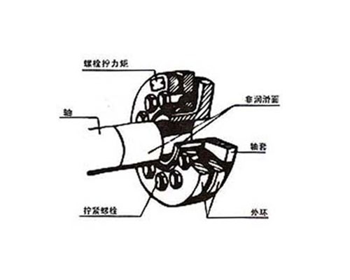
【Product scope and description】

The selection and selection of the lock plate
One
When the diameter of the first design according to the design requirements, the selected axis diameter (DW) in the product catalog and check the locking plate, the maximum transmission torque and the corresponding torque (Mt) whether it can meet the needs.
On the other hand, if the torque is the first requirement, select the desired torque (Mt) from the catalog according to the appropriate model, and then find the corresponding shaft diameter (DW).
II
Check the size and strength of the shaft and shaft sleeve according to the lock plate.
The outer diameter (d) of the shaft sleeve or hollow shaft is consistent with the inner diameter of the locking plate. The minimum cross section of the shaft sleeve can safely deliver the specified torque.
III
The rated torque Mt listed in the catalogue and the Pax value of the nominal axial load are listed in accordance with the maximum value which can be transmitted by the locking plate, and the safety factor should not be considered.
IV
Drive torque value (Mt) and shaft diameter (DW) on the relationship between the linear functional relationship model catalog, not listed in the table all the corresponding shaft diameter the rated torque can be calculated, but a shaft diameter may the torque transmitted by interpolation.
Illustrate:
To connect a 103mm shaft, to install a locking plate, the maximum transmission torque is determined to be 12400Nm, select the lock plate model specifications.
Step 1: the diameter of the shaft is close to 100mm. ,
The second step: in the standard series 71 type specification table, find out the shaft diameter 100mm corresponding locking disc model is SD140-71, with the interpolation method to calculate the 103mm axis can transfer the maximum torque of 17600Nm and 20100Nm between 19100Nm.
The third step: verify the size of the lock plate, and design on the drawings.
The fourth step: to find out the processing tolerance and the applicable way.
Namely: shaft and shaft sleeve bore tolerance is H7/h6, shaft diameter is f7.
The fifth step: the use of locking plate, according to the following types of orders: locking plate SD140-71.
Matters needing attention:
In order to ensure that the table of contents listed in the torque and axial load value, design drawings, it must be noted that the tightening screw tightening torque according to the provisions of Ma is very important.
Because the locking plate and screw are only static force, do not have to worry about the screw.
Installation and disassembly
The locking plate is ready to be installed before the factory, so it is not necessary to disassemble before the first installation;
1, remove the protective effect of transport in the outer ring of the middle partition.
2, take any of the three locking screws to form an isosceles triangle, and they are gently tightened, until the inner ring can still be turned on, too much force will lead to tighten the inner ring plastic deformation.
3, so that the lock plate sliding on the shaft sleeve, the outer ring can grease lubrication. ,
Note: remember to tighten the screws before installing the shaft into the shaft sleeve.
4, clean the shaft and shaft sleeve hole grease.
5, the shaft into the shaft hole grease.
6, the use of force measuring plate hand tighten all locking screws. Tightening method is in order to gradually tighten the love, each time only to the rated torque of 1/4.
It is very important to check the tightening torque Ma with torque. The two locking rings must be equidistant.
Disassembly sequence
1, gradually loosen all the locking screws, each cycle of the screw loose 1/4. Do not completely remove the fastening screws. ,
2, remove the shaft or take off the shaft from the shaft, the shaft in the front of the first set of rust must be removed.
3, remove the lock plate from the shaft sleeve.
4, the removal of the lock plate does not have to completely break down, do not need lubrication before reloading. Molybdenum disulfide (MOS2) lubricant for cone surface. Molybdenum bearing grease for locking screws. Damaged O shape must be changed.
.
